- 您现在的位置:买卖IC网 > Sheet目录3753 > ATMEGA169P-16MCHR (Atmel)MCU AVR 16KB FLASH 16MHZ 64-VQFN
40
8018P–AVR–08/10
ATmega169P
9.
Power Management and Sleep Modes
Sleep modes enable the application to shut down unused modules in the MCU, thereby saving-
power. The AVR provides various sleep modes allowing the user to tailor the power
consumption to the application’s requirements.
9.1
Sleep Modes
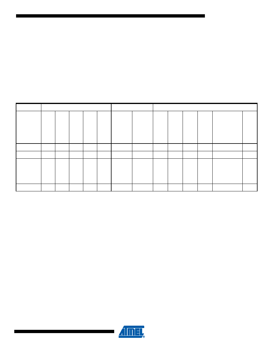
Figure 8-1 on page 30 presents the different clock systems in the ATmega169P, and their distri-
bution. The figure is helpful in selecting an appropriate sleep mode. Table 9-1 shows the
different sleep modes and their wake up sources.
Notes:
1. Only recommended with external crystal or resonator selected as clock source.
2. If either LCD controller or Timer/Counter2 is running in asynchronous mode.
3. For INT0, only level interrupt.
To enter any of the sleep modes, the SE bit in SMCR must be written to logic one and a SLEEP
instruction must be executed. The SM2, SM1, and SM0 bits in the SMCR Register select which
sleep mode will be activated by the SLEEP instruction. See Table 9-2 on page 45 for a
summary.
If an enabled interrupt occurs while the MCU is in a sleep mode, the MCU wakes up. The MCU
is then halted for four cycles in addition to the start-up time, executes the interrupt routine, and
resumes execution from the instruction following SLEEP. The contents of the Register File and
SRAM are unaltered when the device wakes up from sleep. If a reset occurs during sleep mode,
the MCU wakes up and executes from the Reset Vector.
Table 9-1.
Active Clock Domains and Wake-up Sources in the Different Sleep Modes.
Active Clock Domains
Oscillators
Wake-up Sources
Sleep
Mode
cl
k
CPU
cl
k
FLASH
cl
k
IO
cl
k
ADC
cl
k
ASY
Mai
n
Cloc
k
So
ur
ce
E
n
ab
led
Ti
m
e
rOs
c
Enab
led
IN
T0
an
d
Pin
Cha
n
g
e
US
IS
ta
rt
C
ond
itio
n
LC
D
C
ont
ro
ll
er
Ti
m
e
r2
SPM/
EEPR
OM
R
ead
y
AD
C
Ot
her
I/O
Idle
XXX
X
XXXX
XXX
ADC NRM
X
XX(2)
X(2)
XX
Power-
down
X
Power-
save
XX
XXX
Standby(1)
X
发布紧急采购,3分钟左右您将得到回复。
相关PDF资料
2-1546217-0
TERM BLK RCPT 20POS SIDE 5.08MM
1-1546217-9
TERM BLK RCPT 19POS SIDE 5.08MM
1-1546217-8
TERM BLK RCPT 18POS SIDE 5.08MM
1-1546217-7
TERM BLK RCPT 17POS SIDE 5.08MM
1-1546217-6
TERM BLK RCPT 16POS SIDE 5.08MM
1-1546217-5
TERM BLK RCPT 15POS SIDE 5.08MM
1-1546217-4
TERM BLK RCPT 14POS SIDE 5.08MM
1-1546217-3
TERM BLK RCPT 13POS SIDE 5.08MM
相关代理商/技术参数
ATMEGA169P-16MCU
功能描述:8位微控制器 -MCU AVR 16KB, 512B EE 16MHz 1KB SRAM, 5V
RoHS:否 制造商:Silicon Labs 核心:8051 处理器系列:C8051F39x 数据总线宽度:8 bit 最大时钟频率:50 MHz 程序存储器大小:16 KB 数据 RAM 大小:1 KB 片上 ADC:Yes 工作电源电压:1.8 V to 3.6 V 工作温度范围:- 40 C to + 105 C 封装 / 箱体:QFN-20 安装风格:SMD/SMT
ATMEGA169P-16MU
功能描述:8位微控制器 -MCU AVR 16K FLASH 512B EE 1K SRAM LCD ADC RoHS:否 制造商:Silicon Labs 核心:8051 处理器系列:C8051F39x 数据总线宽度:8 bit 最大时钟频率:50 MHz 程序存储器大小:16 KB 数据 RAM 大小:1 KB 片上 ADC:Yes 工作电源电压:1.8 V to 3.6 V 工作温度范围:- 40 C to + 105 C 封装 / 箱体:QFN-20 安装风格:SMD/SMT
ATMEGA169P-16MU SL383
制造商:Atmel Corporation 功能描述:MCU 8BIT ATMEGA RISC 16KB FLASH 3.3V/5V 64PIN MLF - Tape and Reel
ATMEGA169P-16MUR
功能描述:8位微控制器 -MCU AVR LCD 16KB FLSH EE 512B 1KB SRAM-16MHZ RoHS:否 制造商:Silicon Labs 核心:8051 处理器系列:C8051F39x 数据总线宽度:8 bit 最大时钟频率:50 MHz 程序存储器大小:16 KB 数据 RAM 大小:1 KB 片上 ADC:Yes 工作电源电压:1.8 V to 3.6 V 工作温度范围:- 40 C to + 105 C 封装 / 箱体:QFN-20 安装风格:SMD/SMT
ATMEGA169P-8AU
制造商:ATMEL 制造商全称:ATMEL Corporation 功能描述:Microcontroller with 16K Bytes In-System Programmable Flash
ATMEGA169P-8MU
制造商:ATMEL 制造商全称:ATMEL Corporation 功能描述:Microcontroller with 16K Bytes In-System Programmable Flash
ATMEGA169PA
制造商:ATMEL 制造商全称:ATMEL Corporation 功能描述:8-bit Microcontroller with 16K Bytes In-System Programmable Flash
ATMEGA169PA_1
制造商:ATMEL 制造商全称:ATMEL Corporation 功能描述:High Endurance Non-volatile Memory segments